Joint industry project on steel riser fatigue
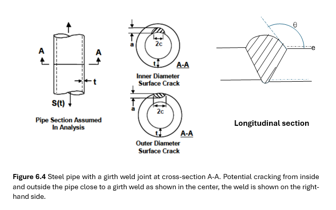
Offshore steel risers are often subjected to harsh environment and variable repetitive loading during service life. The associated variations in stresses and strains in the pipe wall may give fatigue cracks, particularly close to the girth welds that are joining the pipe segments. The potential cracks are sketched up in Figure 6.4 and they may occur both from the external toe of the weld cap or from the weld root as shown. It must be ensured at the design stage that these potential cracks do not initiate and grow to sizes that represent a threat to the integrity of the steel riser during the target service life. Such fatigue damage may give production loss, unacceptable repair costs and even endanger human safety. On this background a Joint Industry Project (JIP) led by The Welding Institute (TWI) and Det Norske Veritas (DNV) has been initiated. The goal is to provide more scientific insight into the actual fatigue damage mechanism such that more accurate and reliable life prediction models can be established. Furthermore, the guidelines and the recommendations that are given in various building codes should be harmonized. Marinres has been asked to join the project to contribute to this important work. The JIP is funded by oil & gas companies.
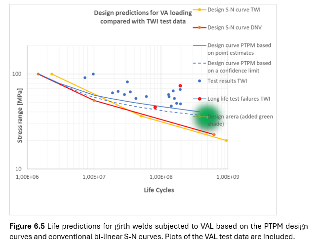
Marinres shall use a Random Fatigue Limit Model (RFLM) to solve the problems discussed above. The RFLM represents an alternative to the common statistical analysis used as basis for the conventional S-N cures. An important characteristic of the RFLM is that both the finite life N and the fatigue limit S0 are treated as random variables simultaneously. This will result in a non-linear S-N curve for a log-log scale. If the scatter at long live increases, this will be revealed by the model. Furthermore, the existence of a fatigue limit may be accepted or rejected based on the obtained model. As the RFLM is using a maximum likelihood approach, the run-out data can easily be included. The RFLM will give more reliable selection of the transition point between upper and lower S-N curve. The slope and the scatter pertaining to the lower curve can also be more accurately determined. Hence, the RFLM can be used to assist the construction of the conventional S-N curves. Furthermore, based on the RFLM, a Probabilistic Two-Phase Model (PTPM) can be established. This model that may account for the existence of a crack initiation phase, is a stand-alone model for life predictions and may replace the existing conventional S-N curves. Preliminary PTPM results compared with data from VAL testing of girth welded pipes are shown in Figure 6.5. As can be seen, the predictions made by the PTPM are closer to the test data and they are substantially longer than the predictions made by the conventional S-N curves. These results are promising but need to be corroborated during the present JIP. More VAL test data for welded pipes should be provided.
Lightwind Project: Generator for offshore wind turbines
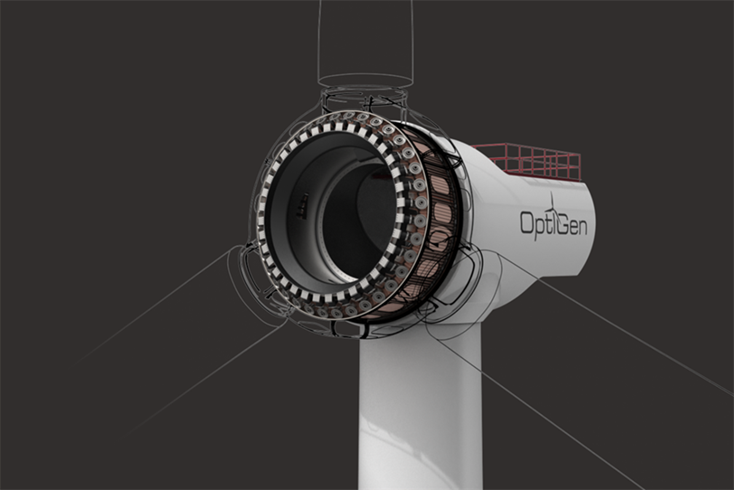
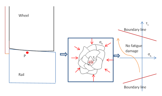
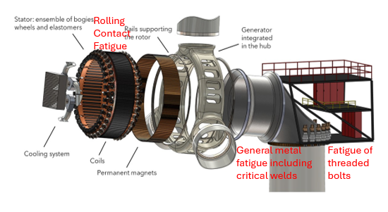
The goal of the project is to seek an optimized generator design with low weight and costs that gives high reliability throughout the planned service life. The design of the drive-train bearing is the essence of the project and the reliability against potential time-dependent damage mechanisms is analyzed and verified in test lab at the Fraunhofer institute in Hamburg. The Optigen company, situated in Barcelona, is conducting the design process. The preliminary design that was published in Windpower Monthly is visualized in Figure 6.1. The chosen design can greatly reduce the costs associated with offshore wind energy whilst high reliability is maintained. As the chosen bearing design deviates substantially from a conventional bearing, new models for wear and fatigue analysis are developed. The main contribution from Marinres is to establish a methodology and a model for life prediction related to Rolling Contact Fatigue (RCF) in the main bearing. The prediction model is based on Dang Van’s criterion for multiaxial fatigue. Detailed stress analysis is carried out in the contact zone between the wheels and rail; the principles for the prediction model are sketched up in Figure 6.2. Figure 6.3 indicates structural details where detailed fatigue analyses are carried out. The project is funded by the Horizon program in the EU and has a 3-years’ timeframe that started in October 2024.
Top picture: Sketch of optimized generator for offshore wind turbines, Ref. Windpower Monthly July 2025
Middle picture: Principal sketch for the Dang Van multiaxial fatigue criterion in the wheel-rail contact zone
Bottom picture: Principal sketch for the Dang Van multiaxial fatigue criterion in the wheel-rail contact zone


Risk-based inspection planning for fatigue damage
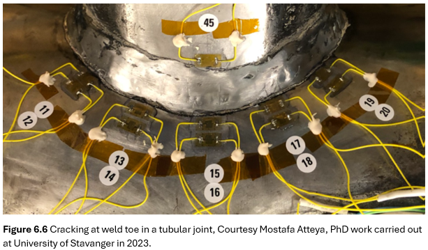
Obtaining high reliability against fatigue damage is one of the most important design criteria for offshore steel structures. Due to repeated stress and strains caused by wind and wave loading, fatigue cracks may initiate and grow in critical structural items such as welded joints and threaded bolts. The final fracture may lead to total collapse for non-redundant structures. A typical fatigue crack in a tubular joint with perpendicular pipe axes is shown in Figure 6.6. As can be seen, the cracks have initiated close to the weld toe and grown into the pipe wall.
The common strategy for obtaining high reliability throughout service life is to achieve a good initial design with high fatigue resistance. In addition, it must be ensured that the few cracks that may occur do not reach a critical crack size before repair is carried out. This latter requirement is handled by establishing a scheduled inspection program based on the principles of risk-based inspection (RBI) planning. An appropriate inspection method is selected, and an associated inspection interval is chosen such that the reliability against fracture is maintained.
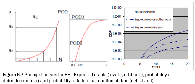
The principles of risk-based inspection planning are shown in Figure 6.7 below. The models are based on applied fracture mechanics and probability theory. The likely crack growth over time must be known (left curve) together with the probability of detection for the applied inspection technique (in the center). Failure probability over time for a given inspection program is obtained as shown to the right.
The results to the right in Figure 6.7 are often presented by the reliability curves as shown in Figure 6.8 and Figure 6.9. Figure 6.8 gives the results from the RBI analysis at the design stage when no inspection results are known. In Figure 6.9 the results from the first inspection are known. The first information from this inspection is usually that the structural detail has survived, and in addition the inspection outcomes can be:
· Outcome A Crack detected and repaired
· Outcome B No cracks found
· Outcome C Cracks detected without repair
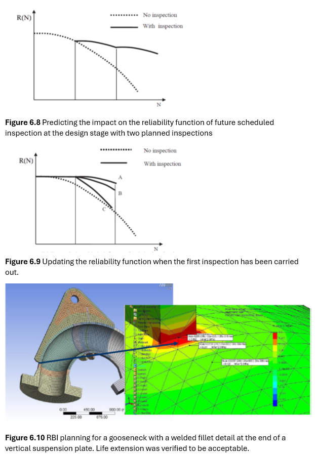
Based on these outcomes the reliability model is updated. The methodology has been applied for a welded detail in a gooseneck pipe that is used in a loading system for crude oil in the North Sea, see Figure 6.10. The objective was to verify if life extension was acceptable when inspections are planned and carried out. The critical details are the terminations of the vertical suspension plate at the upper surface of the main pipe that conducts the oil-flow. By using the principles for RBI described above it was found that the gooseneck could be kept in service provided that Magnetic Particle Inspection (MPI) was carried out every 10 years in good workshop environment. Every crack detection must lead to a high-quality repair. The gooseneck is still in service.